| Yaesu FT-101Z(D) "aftermarket" frequency counter
Back to S56AL main page!
|
|
|
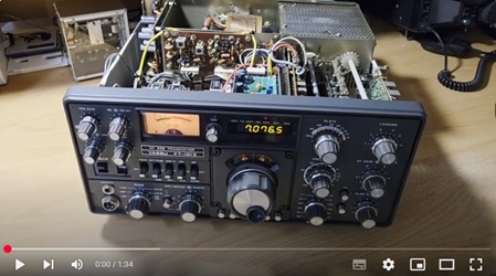
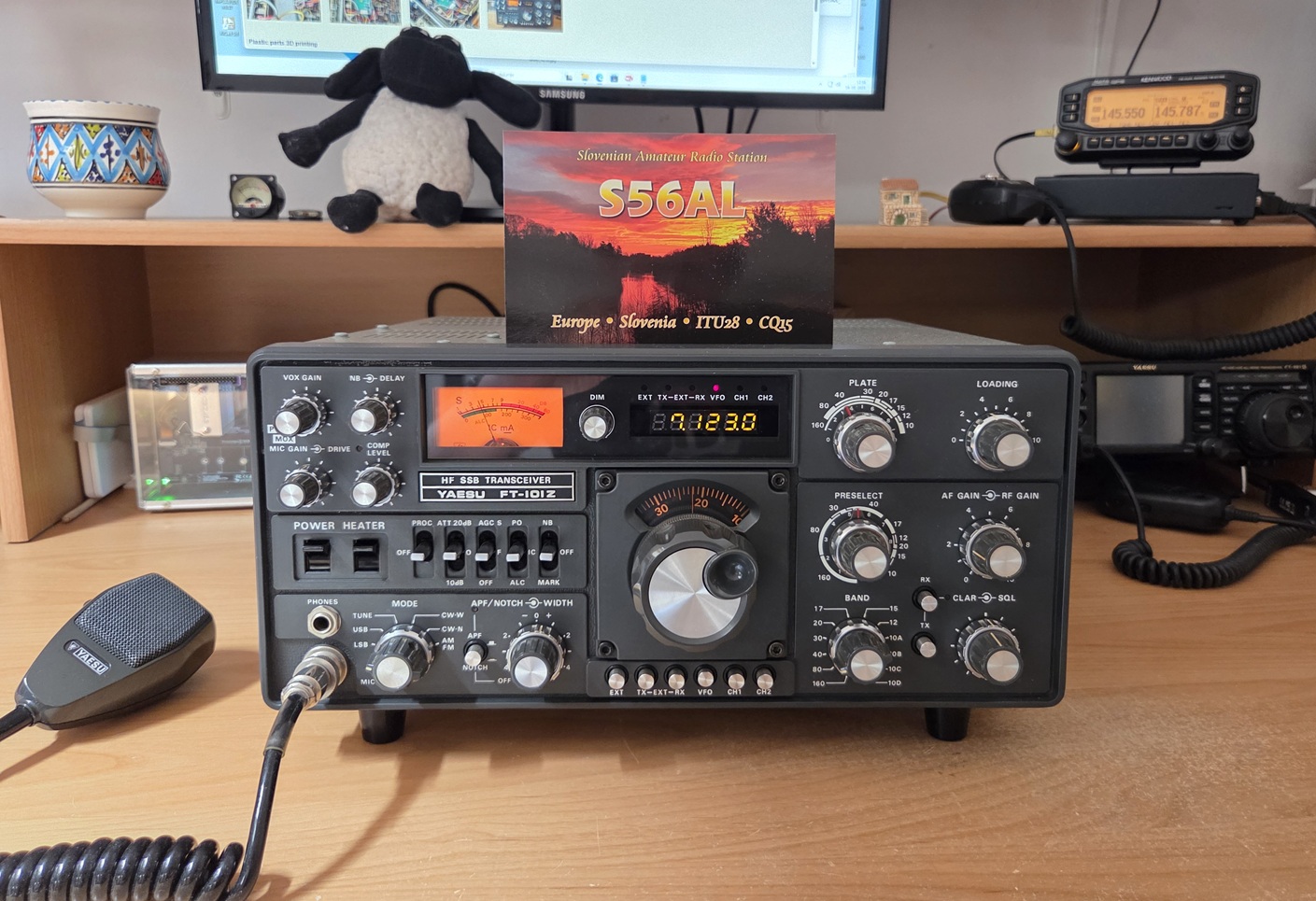
Some time ago, a well-preserved Yaesu FT-101Z transceiver appeared at a local flea market. In the early 80s of the last century, when I started my amateur radio activities, the then popular FT-101Z(D) transceiver looked like a "spaceship" and far out of reach for a newbie like me. Therefore, even after all these years, I could not resist buying it when I found one ;). Following the design of the aftermarket frequency counter for the TS-820(S) built two years ago, I decided to design and build a digital frequency counter for the recently acquired FT-101Z as well.
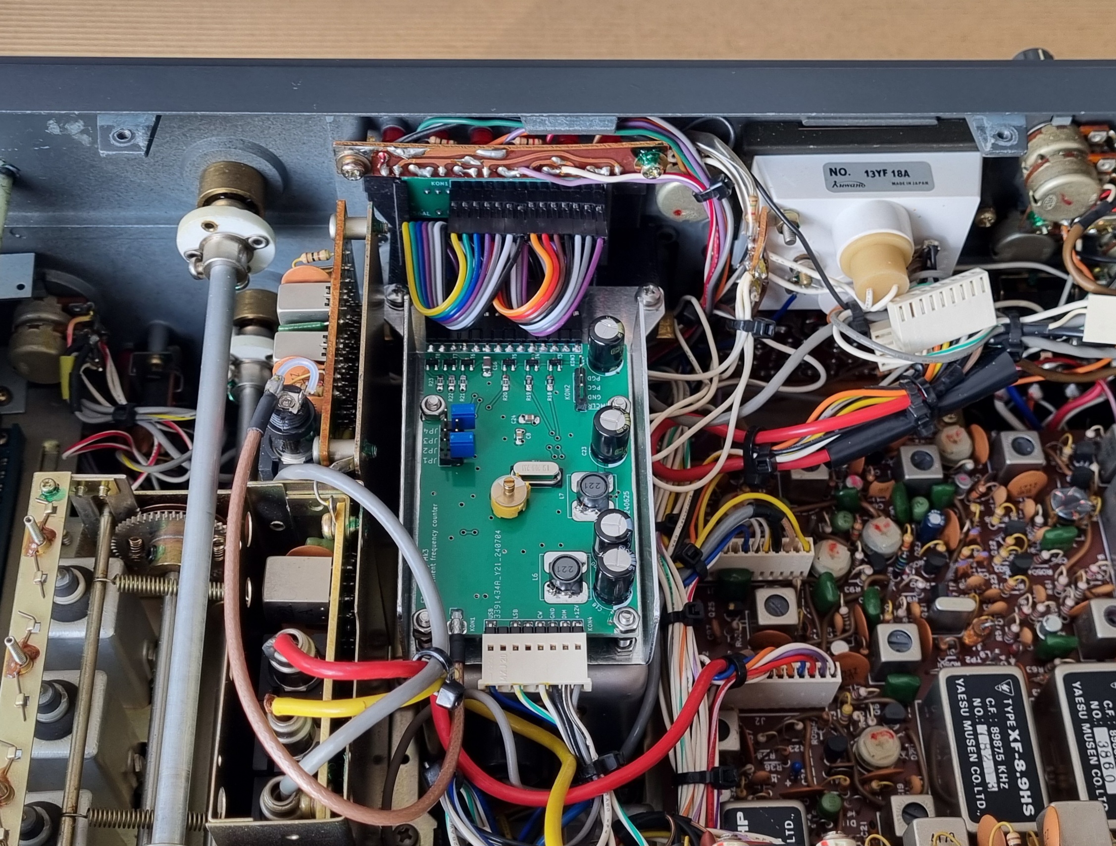
My FT-101Z transceiver is one of the latest versions (Mk3). I have no idea if the counter would mechanicaly fit the earlier versions of the FT-101Z transceivers. As far as I know, at least the header connector (KON4) would have to be adapted to the earlier transceiver version(s).
Let me point out that this is not a commercial product. I do not sell either built devices or KITs!
Version 1.0 - release June, 2024
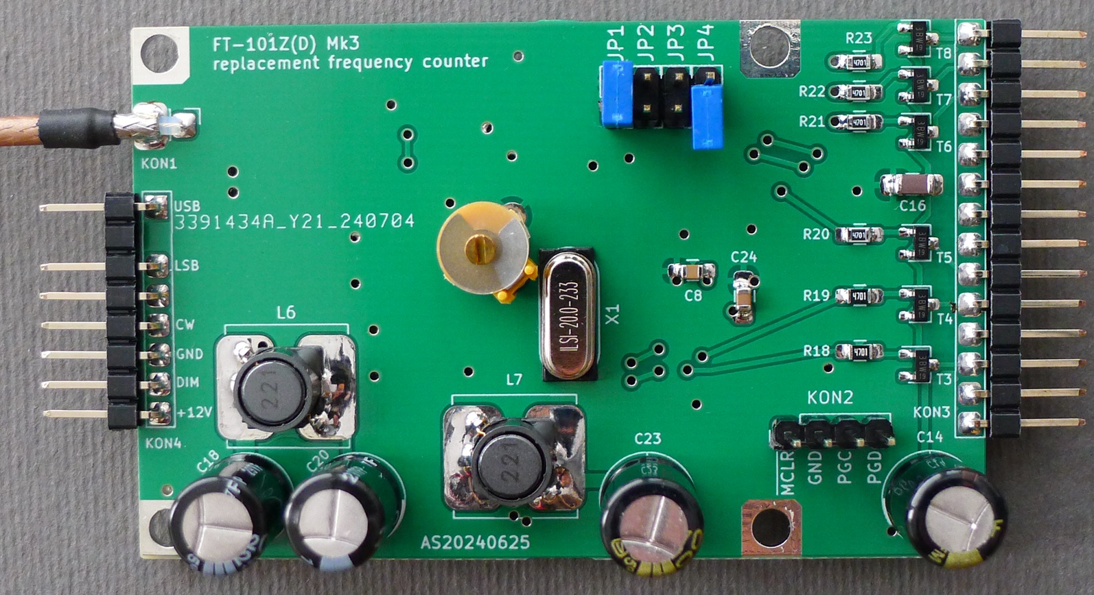
Unlike its "bigger brother" designed for the TS-820(S), the FT-101Z counter only needs to measure the frequency of one (VFO) signal. The IF offset is programmed in the software as a set of constant values, selected depending on the position of the operating mode switch, subtracted from the measured VFO frequency and displayed on the 6-digit 7-segment LED unit.
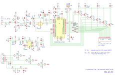
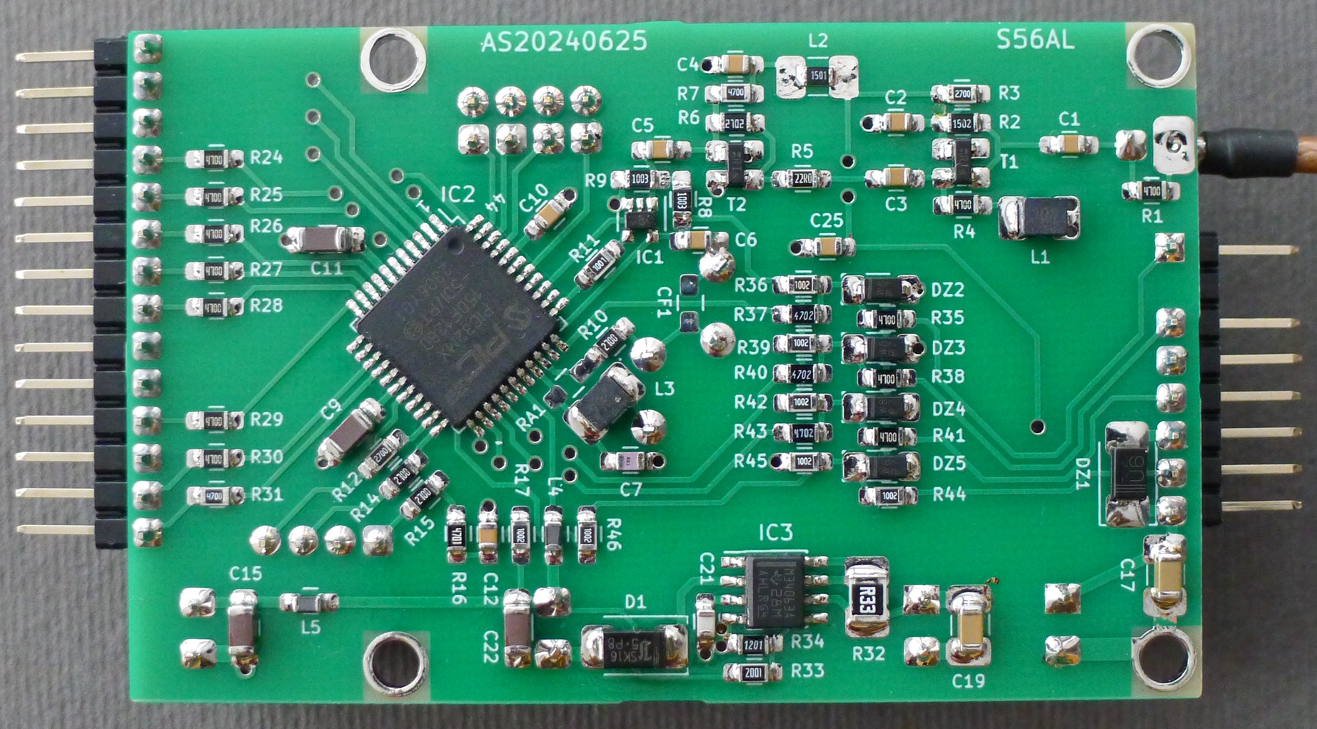
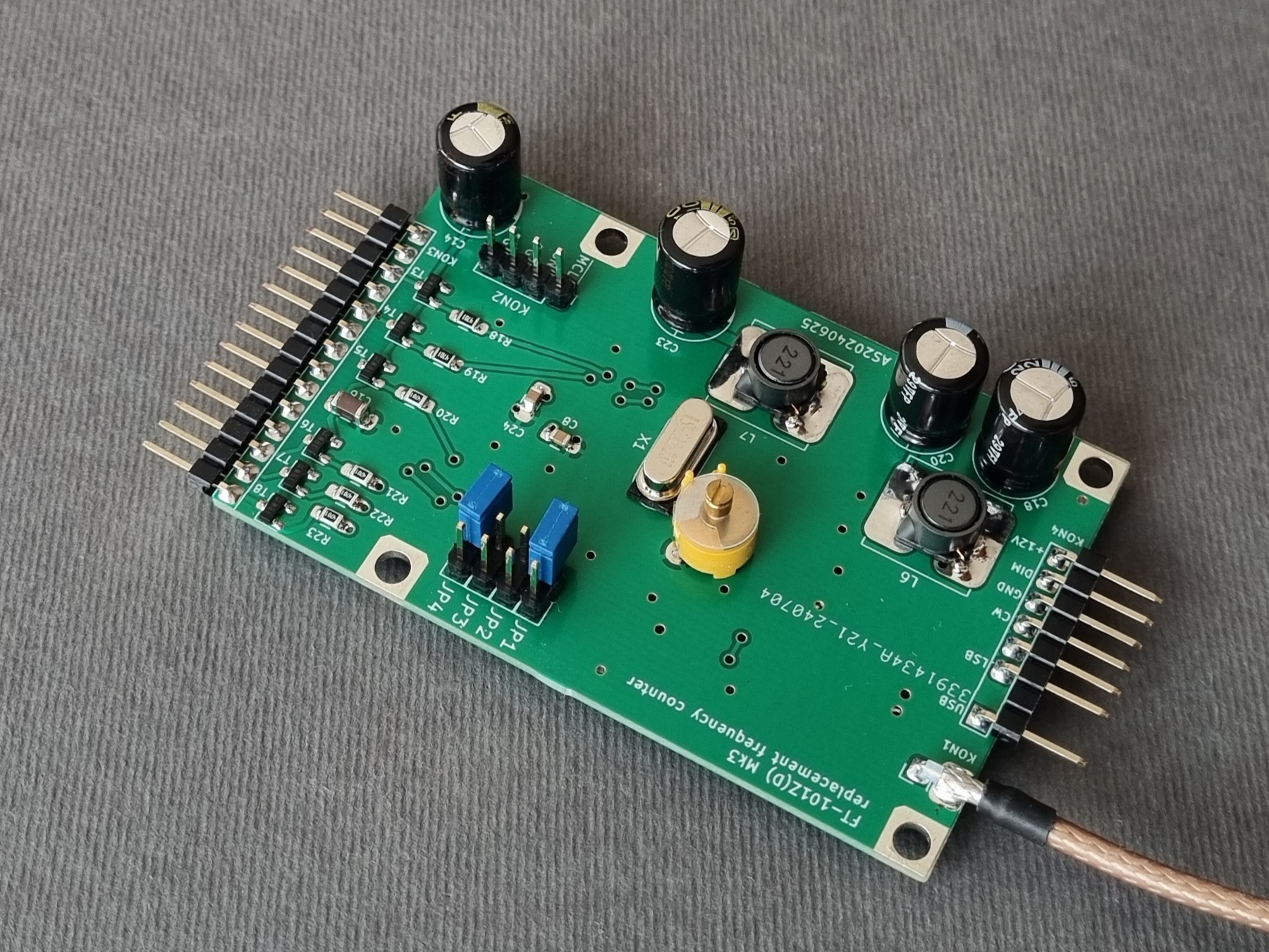
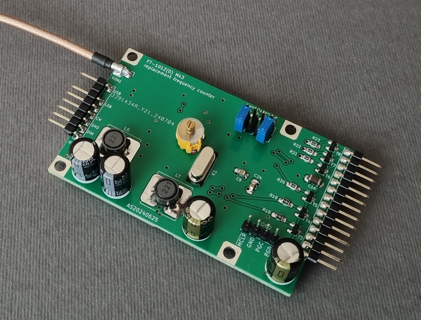
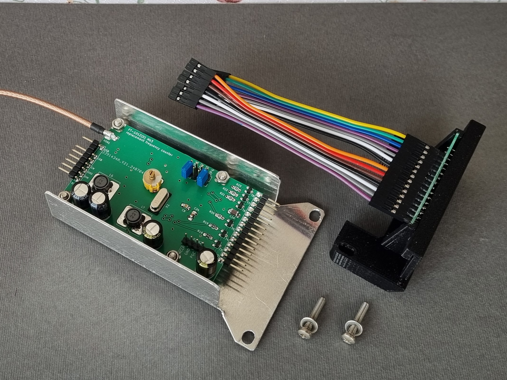
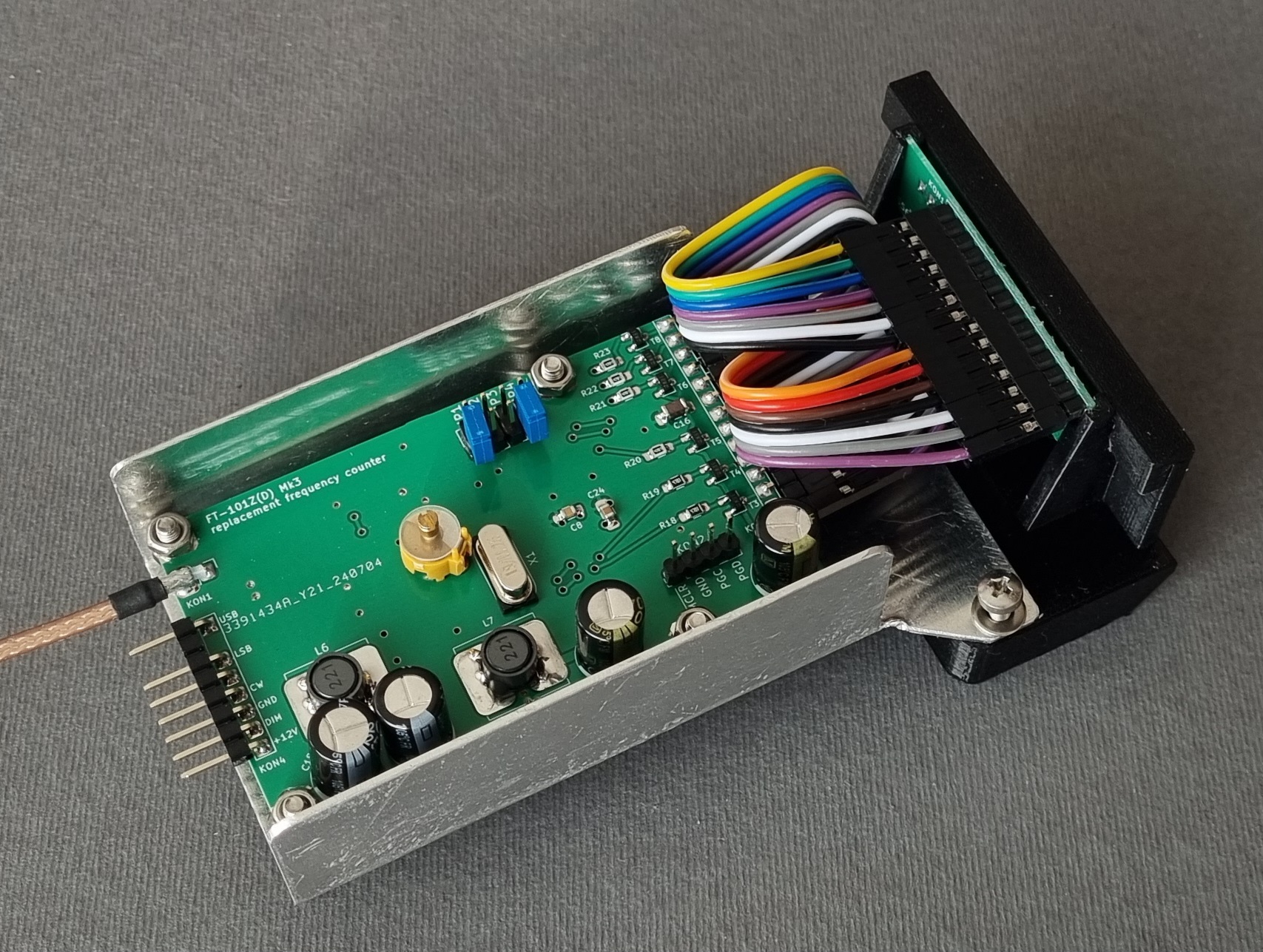
The counter is built on a 1,6 mm thick double sided FR4 PCB. The circuit schematics as well as assembly photos of top and bottom side speak for themself and are shown in the images below.
 |
 |
 |
 |
 |
The PCB Gerbers and firmware HEX files are available to licenced radio amateurs for non-commercial / personal use per E-mail request!
Jumper settings table (Firmware release V1.0)
| JP1 | JP2 | JP3 | JP4 | |
| N.C. | - | - | N.C. | Hold display while switching bands |
| SET | - | - | N.C. | Dimm display while switching bands |
| - | - | - | SET | Frequency callibration mode |
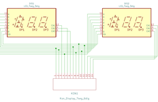
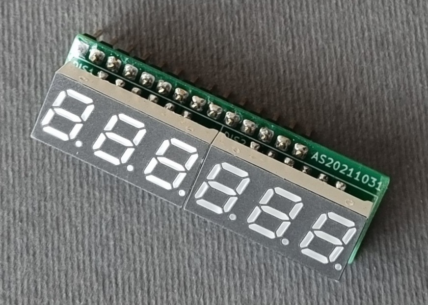
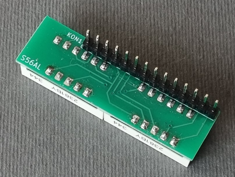
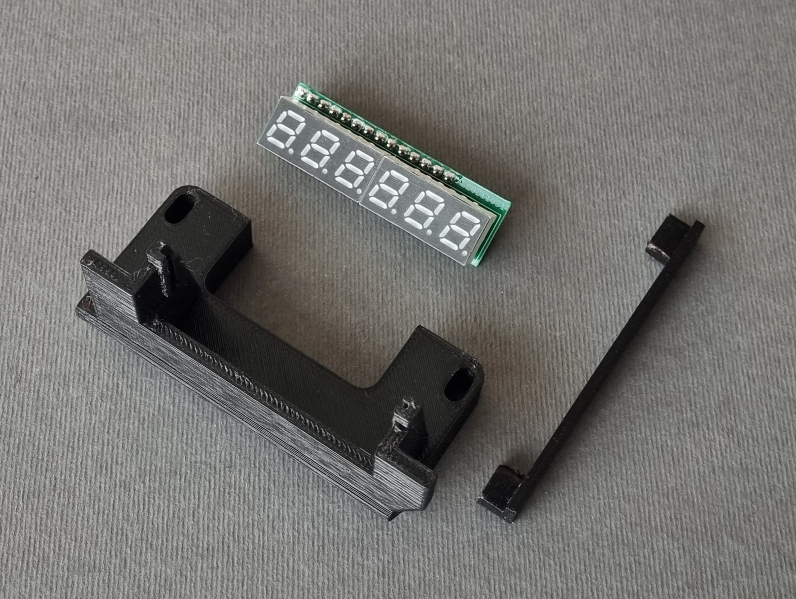
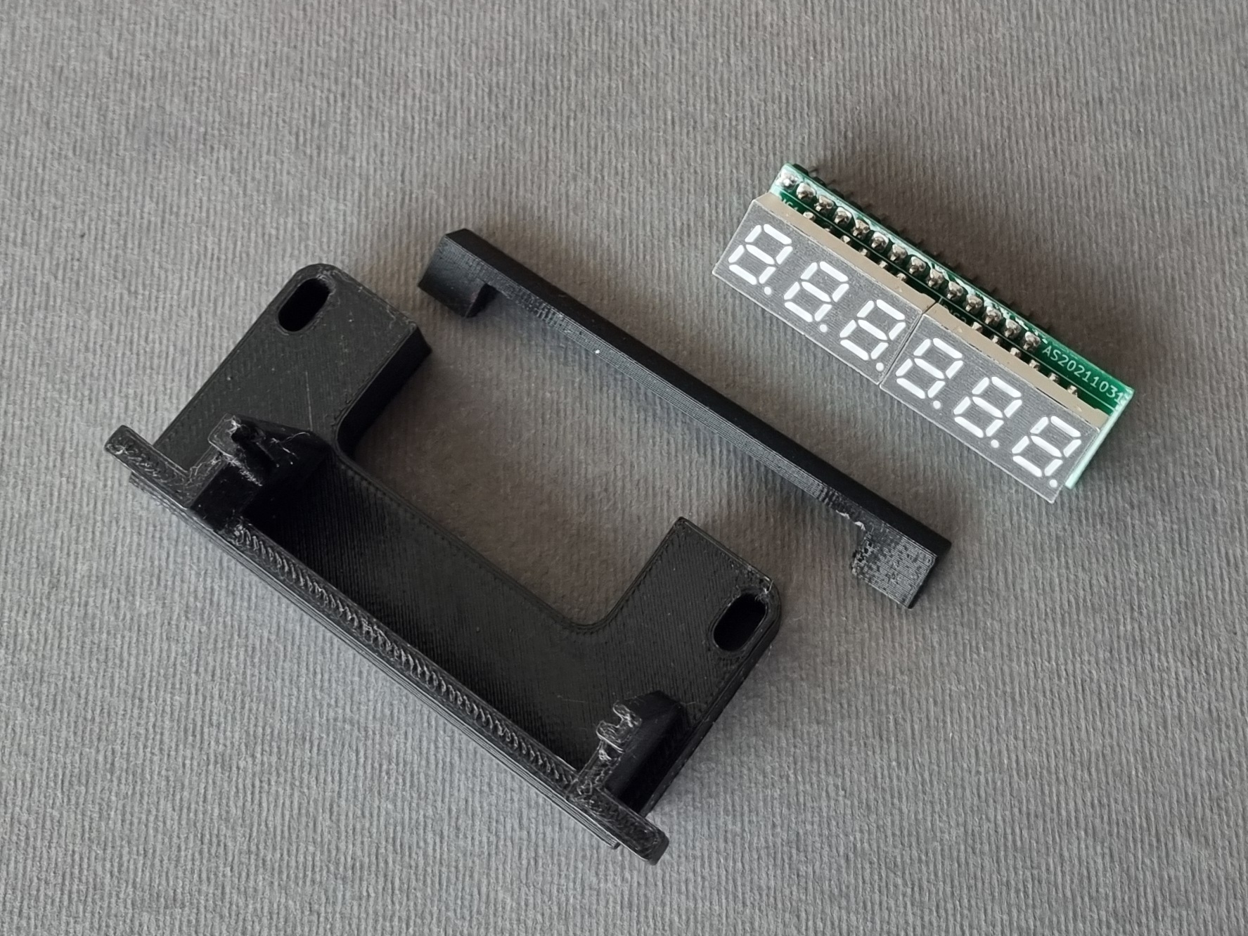
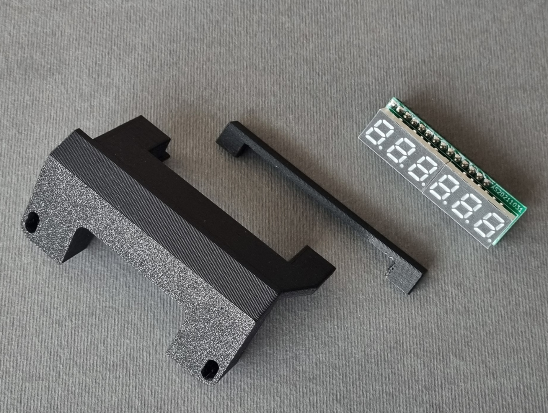
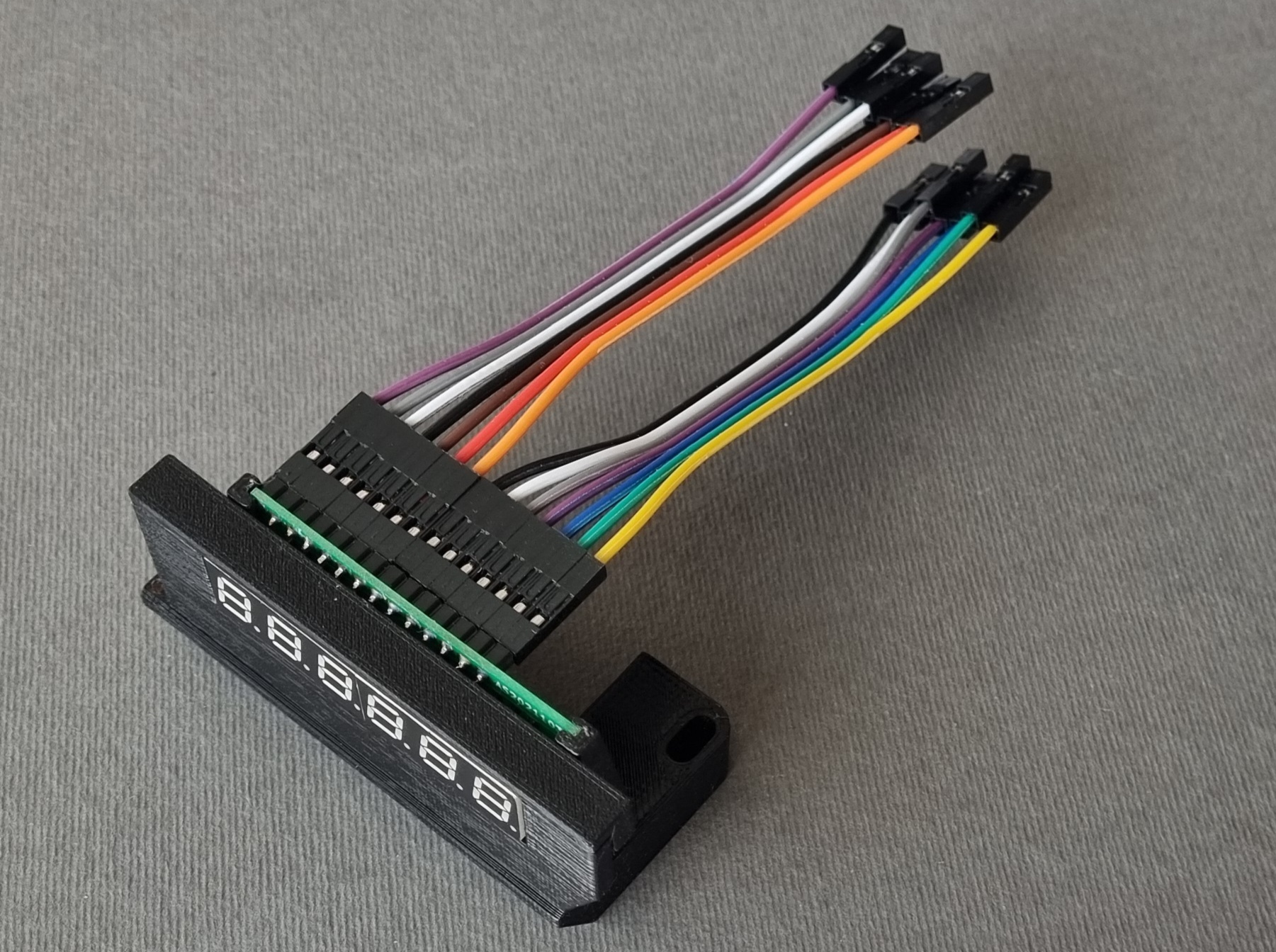
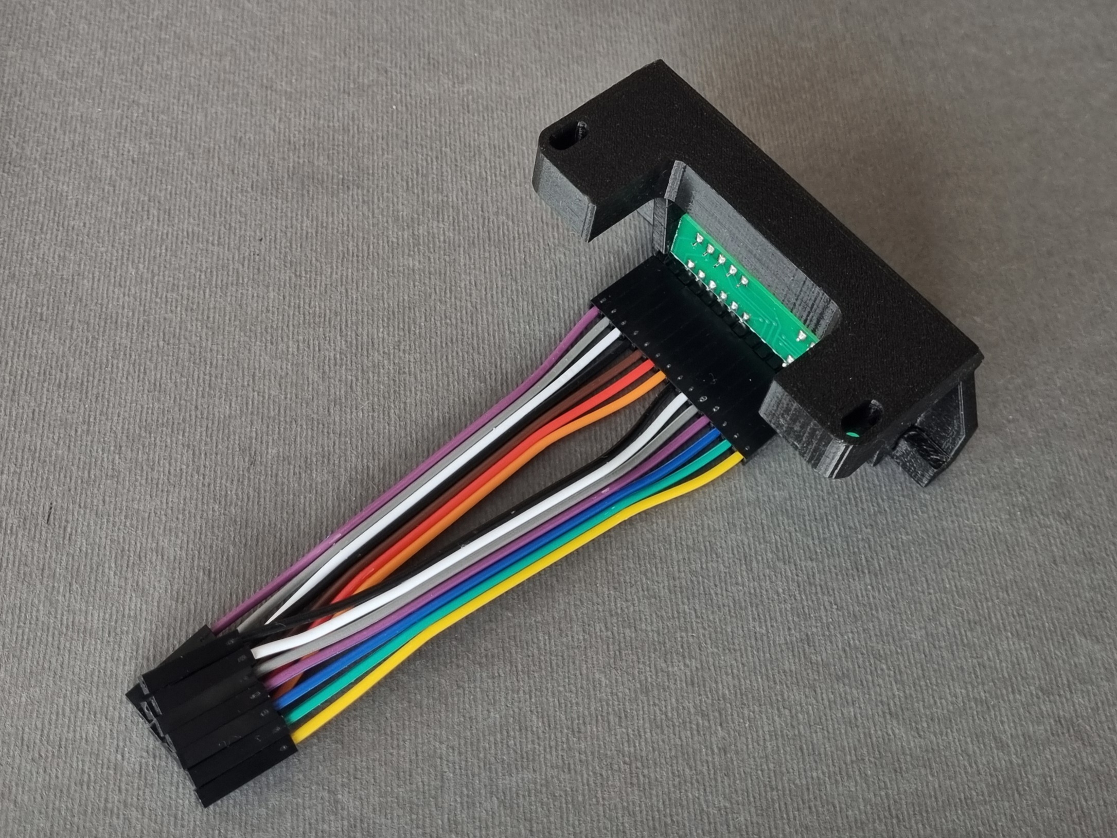
Display unit
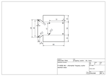
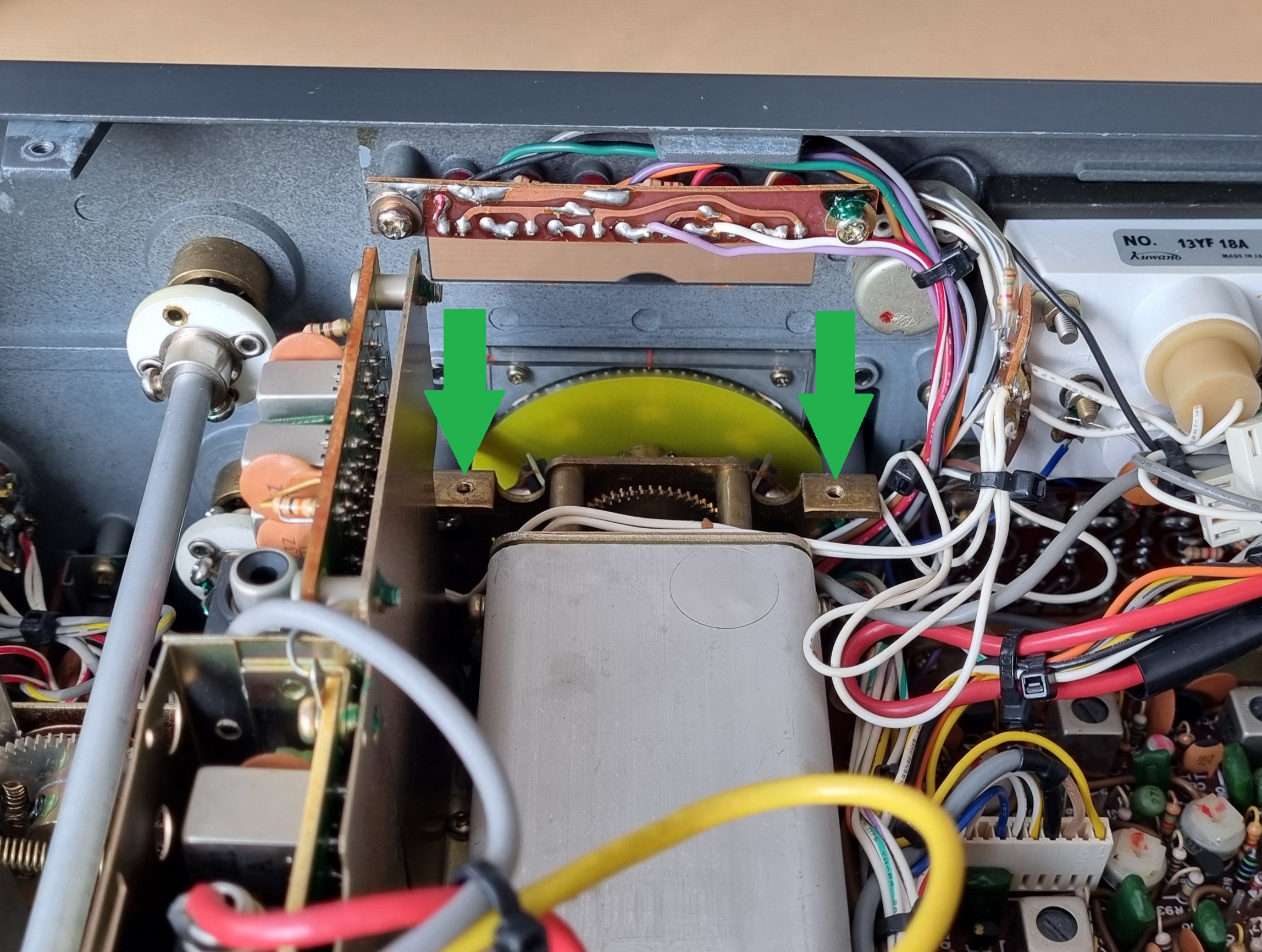
The printed circuit board of the 0.28 inch display unit was taken from the "TS-820(S) aftermarket counter" project and is made of 1 mm thick FR4 laminate. The plastic display bracket had to be redesigned to fit perfectly to the front panel of the FT-101Z Mk3 transceiver. The bracket was attached to the existing M3 screw holes in the transceiver's chasis with two M3 screws. No modification to eitheir transceiver's housing or chasis was needed.
 |
 |
 |
 |
 |
 |
 |
 |
| Display unit 0,28" PCB layout - Gerber files (15 kB - zip) |
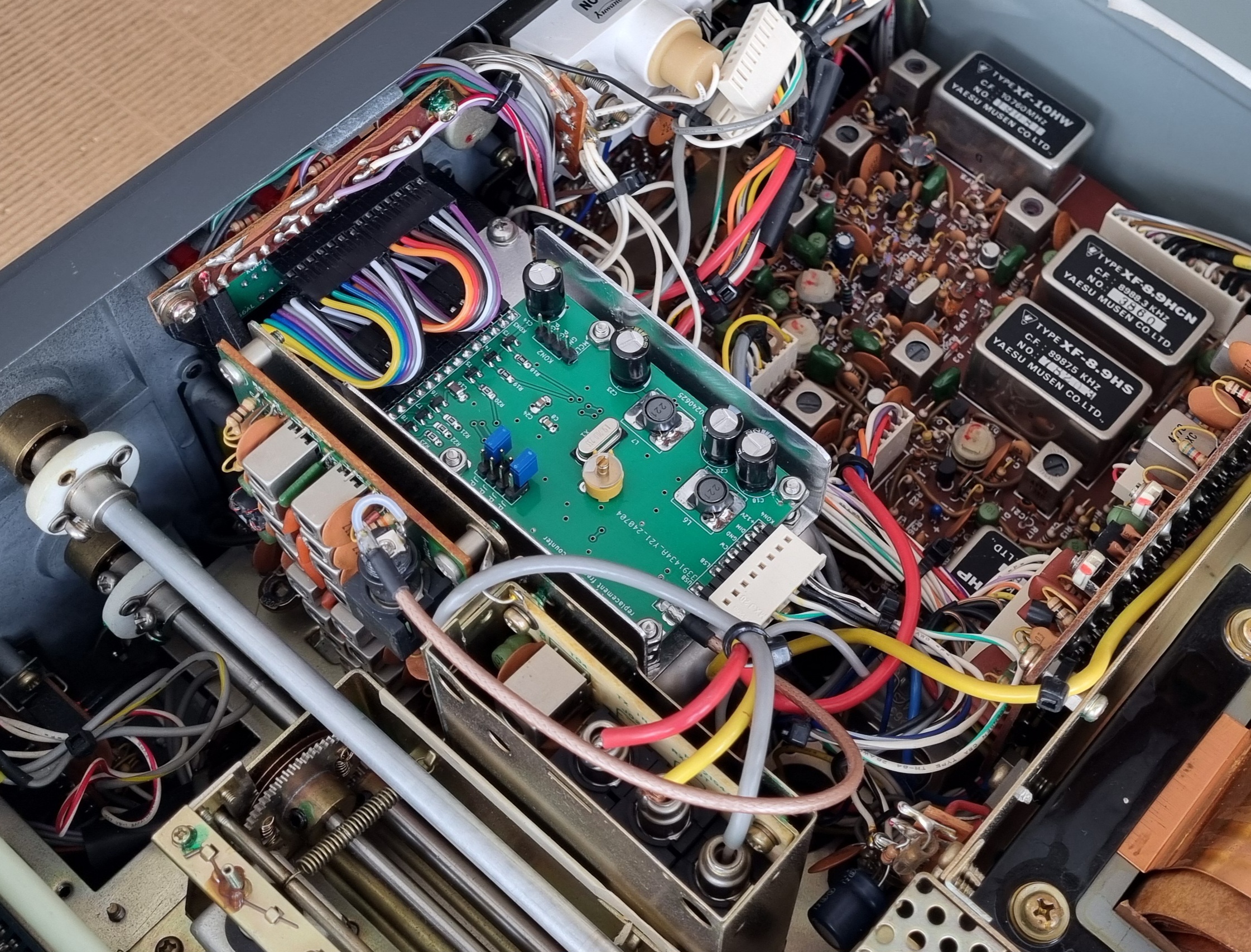
Installation
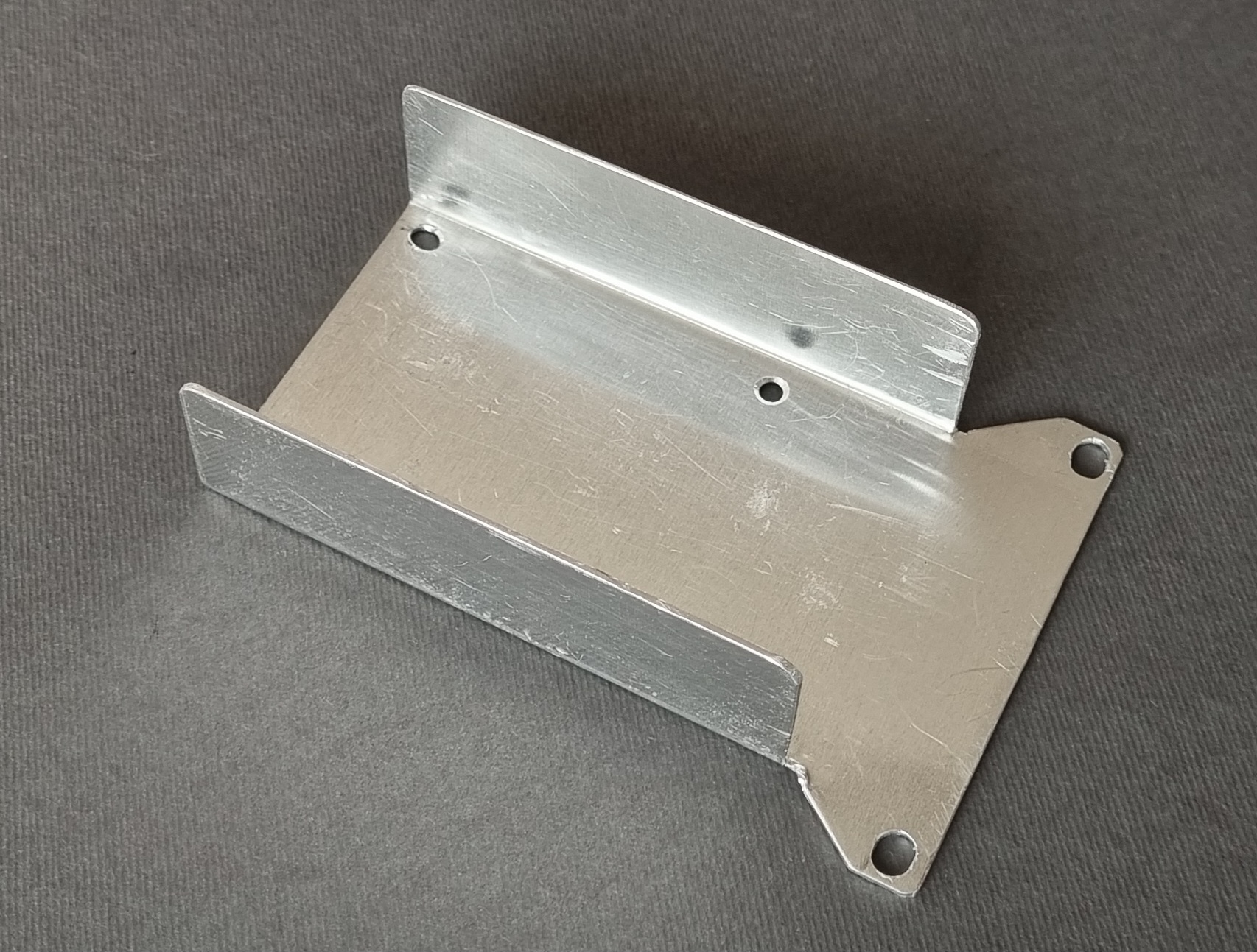
The counter is mounted on a chassis cut and bent out of 1mm thick aluminum sheet.
 |
 |
 |
 |
 |
 |
 |
|
Plastic parts 3D printing
3D printing of the plastic parts in the PLA should be good enough in most cases. If operation in a higher temperature environment is expected, a more resistant PETG should be used instead.
| Plastic parts - STL files for 3DP (5 kB - zip) | |
| Back to S56AL main page! |
| ...counting since May, 2022. |